Control Plane Policing Implementation Best Practices
ContentsIntroduction Introduction: Network Device OperationsIP networks provide users with connectivity to networked resources such as corporate servers, extranet partners, multimedia content, the Internet, and any other application envisioned within IP networks. While these networks function to carry data plane (user-generated) packets, they are also created and operated by control plane and management plane packets. Unlike legacy network technologies such as ISDN, Frame Relay, and ATM that defined separate data and control channels, IP carries all packets within a single pipe. Thus, IP network devices such as routers and switches must be able to distinguish between data plane, control plane, and management plane packets to treat each packet appropriately. From an IP traffic plane perspective, packets may be divided into four distinct, logical groups:
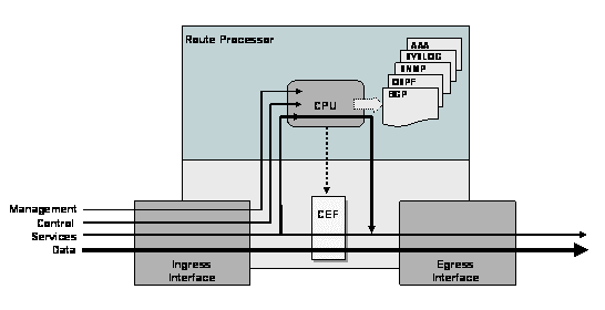
Each of these types represents a specific group of packets that a network device will receive on ingress from network interfaces and be required to process. This concept is illustrated in Figure 1. Figure 1. IP Network Traffic Planes and Their Handling within the Router
Under normal network operating conditions, the vast majority of packets handled by network devices are data plane packets. These packets are handled in the fast path. Network devices are optimized to handle these fast path packets efficiently. Typically, considerably fewer control and management plane packets are required to create and operate IP networks. Thus, the punt path and route processor are significantly less capable of handling the kinds of packets rates experienced in the fast path since they are never directly involved in the forwarding of data plane packets. When high packet rates overload the control and/or management plane, route processor resources can be overwhelmed, reducing the availability of these resources for tasks critical to the operation and maintenance of the network. For example, if a high volume of rogue packets generated by a virus or worm is presented to the control plane, the router will spend an excessive amount of time processing and discarding unnecessary traffic. The route processor is thus not available to support its required tasks such as computing periodic routing table updates, maintaining the CEF table, which is actually used for the forwarding of data plane packets, and maintaining interface link states (see Figure 1). When considering route processor attack scenarios, it is natural to think only of malicious events. However, both malicious and non-malicious events can overwhelm route processor resources. Malicious events include crafted packet attacks or simply high rates of packets directed at the control plane. Non-malicious events may result from router or network misconfigurations, software bugs, or in some circumstances, network failure reconvergence events. From the perspective of the router, the underlying condition is irrelevant when the result is the same. It is important to take appropriate steps to protect the route processor from being overwhelmed, whether by malicious or non-malicious events. Many Cisco IOS™ and Cisco IOS XR software security features are available to protect the route processor of networking devices. Some of these features are generic and applicable to a broad range of security functions. Others are specifically designed to protect the route processor. In brief, important features include the following:
Figure 2. The Impact of Interface ACLs and Control Plane Policing Mechanism on Each IP Network Traffic Plane
The remainder of this white paper provides deployment and operational guidance for the Cisco IOS CoPP feature. A short overview for comparison purposes is also provided for the Cisco IOS XR LPTS feature. Control Plane Policing Feature DescriptionGeneral OverviewControl Plane Policing (CoPP) is a Cisco IOS-wide feature designed to allow users to manage the flow of traffic handled by the route processor of their network devices. CoPP is designed to prevent unnecessary traffic from overwhelming the route processor that, if left unabated, could affect system performance. Route processor resource exhaustion, in this case, refers to all resources associated with the punt path and route processor(s) such as Cisco IOS process memory and buffers, and ingress packet queues. More than just control plane packets can punt and affect the route processor and system resources. Management plane traffic, as well as certain data plane exceptions IP packets and some services plane packets, may also require the use of route processor resources. Even so, it is common practice to identify the resources associated with the punt path and route processor(s) as the Control Plane. The feature in Cisco IOS is CoPP. CoPP protects the route processor on network devices by treating route processor resources as a separate entity with its own ingress interface (and in some implementations, egress also). Because of this behavior, a CoPP policy can be developed and applied only to those packets within the control plane. Unlike interface ACLs, for example, no effort is wasted investigating data plane (transit) packets that will never reach the control plane. This action has a significant simplifying implication on the construction of policies for CoPP. CoPP is implemented using the Cisco IOS Modular QoS CLI (MQC), a highly flexible framework that allows users to create and attach traffic polices to interfaces The Cisco Modular QoS CLI (MQC) mechanisms are used by CoPP to define the classification and policing descriptions for its policies. In this way, in addition to the limited permit and deny actions associated with simple ACLs, specific packets may be permitted but rate-limited when using the MQC structure. For example, you may wish to permit certain ICMP packet types, but rate limit them so that the route processor is not adversely impacted. This action adds tremendously to the capabilities and flexibility of developing and deploying a useable CoPP policy. In general, the configuration information presented here represents the basic set of CoPP functions that should be available across all platforms. Where appropriate, references will be made to areas that may have different behavior or enhanced feature availability. The remainder of this section covers the operational aspects involved with successful CoPP policy construction and deployment. CoPP Policy Construction and Deployment ConceptsBefore describing the details of CoPP policy construction and deployment, some of the important details related to MQC and its operation, especially within the context of CoPP are discussed. In MQC, the class-map command is used to define a traffic class. A traffic class contains three major elements: a name, one or a series of match commands, and an instruction on how to evaluate these match commands. Match commands are used to specify various criteria for classifying packets. Packets are checked to see whether they match the criteria specified in the match commands. If a packet matches the specified criteria, that packet is considered a member of the class and is treated according to the QoS specifications set in the service policy. Packets that fail to meet any of the matching criteria are classified as members of the default class. The instruction for evaluating match commands is specified as either match-any or match-all. When more than one match statement is included, match-any requires that a packet match at least one of the statements to be included in the class. If match-all is used, a packet must match all of the statements to be included in the class. The policy-map command is used to associate a traffic class, defined by the class-map command, with one or more QoS policies. The result of this association is called a service policy. A service policy contains three elements: a name, a traffic class (specified with the class command), and the QoS policies. The purpose of the service policy is to associate a traffic class with one or more QoS policies. Classes included within policy maps are processed top-down. When a packet is found to match a class, no further processing is performed. That is, a packet can only belong to a single class, and it is the first one to which a match occurs. When a packet does not match any of the defined classes, it is automatically placed in the class class-default. The default class is always applied, whether it is explicitly configured or not. The service-policy command is used to attach the service policy, as specified with the policy-map command, to an interface. In the case of CoPP, this is the control-plane interface. Because the elements of the service policy can be applied to packets entering, or in some versions of CoPP, leaving the interface, users are required to specify whether the service policy characteristics should be applied to incoming or outgoing packets. It is important to note that MQC is a general framework used for enabling all QoS throughout Cisco IOS, and not exclusively for CoPP. Not all features available within the MQC framework are available or applicable to CoPP policies. For example, only certain classification (match) criteria are applicable to CoPP. In some instances, there are MQC platform and/or IOS-dependencies that may apply to CoPP. Consult the appropriate product references and configuration guides for any CoPP-specific dependencies.
Each of these steps is discussed in detail below. For each step, guidance based on deployment experience is provided. 1. Constructing the CoPP PolicyFor CoPP policy construction, several steps are required to create the MQC classification and policing functions. These include: access-list construction, class-map construction, and finally, policy-map construction. Access List Construction To define appropriate policies for your CoPP configuration, you need to identify all of the traffic flows and packet rates for those flows that may be seen by CoPP. Typically, ACLs are used for the traffic flow identification task and, in most cases, the protocols as well as the source and destination IP addresses are well known. It is still quite likely that some surprise traffic flows will arise. The definition of these ACLs is one of the most critical steps in the CoPP process. MQC uses these ACLs to define the traffic classes, which in turn become the object of the policy actions (policing). Appropriate granularity in the distribution of protocols within these ACLs allows for better protection of the RP. By recognizing that certain classes will be created, you will see that it is important to define distinct, granular access lists that will be used to define the CoPP classes. Some traffic types are easy; BGP is critical, for example. Other traffic types may not be as straightforward. The typical approach involves grouping traffic flows based on function within the network. Such an approach may include classes:
There are several caveats and key points to keep in mind when constructing your access lists.
Based on the above guidance, you can create ACLs to define traffic. Separate ACLs with unique numbers (or names, if allowed) should be used to represent each class. For initial or pilot CoPP deployments, you may wish to be less restrictive on IP source and destination addresses. Over time and with more experience, refinements may be appropriate. Example ACLs for the above categories follow. Routing – ACL 120 !-- ACL for CoPP Routing class-map ! access-list 120 permit tcp any gt 1024 <router receive block> eq bgp access-list 120 permit tcp any eq bgp <router receive block> gt 1024 established access-list 120 permit tcp any gt 1024 <router receive block> eq 639 access-list 120 permit tcp any eq 639 <router receive block> gt 1024 established access-list 120 permit tcp any <router receive block> eq 646 access-list 120 permit udp any <router receive block> eq 646 access-list 120 permit ospf any <router receive block> access-list 120 permit ospf any host 224.0.0.5 access-list 120 permit ospf any host 224.0.0.6 access-list 120 permit eigrp any <router receive block> access-list 120 permit eigrp any host 224.0.0.10 access-list 120 permit udp any any eq pim-auto-rp ---etc--- for other routing protocol traffic... ! Management – ACL 121 ! – ACL for CoPP Management class ! access-list 121 permit tcp <NOC block> <router receive block> eq telnet access-list 121 permit tcp <NOC block> eq telnet <router receive block> established access-list 121 permit tcp <NOC block> <router receive block> eq 22 access-list 121 permit tcp <NOC block> eq 22 <router receive block> established access-list 121 permit udp <NOC block> <router receive block> eq snmp access-list 121 permit tcp <NOC block> <router receive block> eq www access-list 121 permit udp <NOC block> <router receive block> eq 443 access-list 121 permit tcp <NOC block> <router receive block> eq ftp access-list 121 permit tcp <NOC block> <router receive block> eq ftp-data access-list 121 permit udp <NOC block> <router receive block> eq syslog access-list 121 permit udp <DNS block> eq domain <router receive block> access-list 121 permit udp <NTP block> <router receive block> eq ntp ---etc--- for known good management traffic... ! Normal – ACL 122 !-- ACL for CoPP Normal class-map ! access-list 122 permit icmp any <router receive block> echo access-list 122 permit icmp any <router receive block> echo-reply access-list 122 permit icmp any <router receive block> ttl-exceeded access-list 122 permit icmp any <router receive block> packet-too-big access-list 122 permit icmp any <router receive block> port-unreachable access-list 122 permit icmp any <router receive block> unreachable access-list 122 permit pim any any access-list 122 permit igmp any any access-list 122 permit gre any any ---etc--- for other known good traffic... ! Undesirable – ACL 123 ! -- ACL for CoPP Undesirable class-map ! access-list 123 permit icmp any any fragments access-list 123 permit udp any any fragments access-list 123 permit tcp any any fragments access-list 123 permit ip any any fragments access-list 123 permit udp any any eq 1434 access-list 123 permit tcp any any eq 639 rst access-list 123 permit tcp any any eq bgp rst --- etc. all other known bad things here– ! Catch-All IP – ACL 124 ! -- ACL for CoPP Catch-All class-map ! access-list 124 permit tcp any any access-list 124 permit udp any any access-list 124 permit icmp any any access-list 124 permit ip any any ! The next step in CoPP policy construction is that of class-map construction. Class Map Construction In MQC, the class-map statement defines the classes by name, and includes one or several match statements that indicate the classification mechanisms to be used to determine which packets are in the class. The match keyword supports the following classification mechanisms for CoPP:
Thus, the syntax used within MQC for creating a CoPP class map is as follows: router(config) class-map [match-any | match-all] class-name router(config-cmap) match [access-group | protocol | ip prec | ip dscp] Based on the ACL construction phase, the following classes of traffic are defined for the CoPP policy. ! ! – CoPP Routing class-map ! class-map match-all Routing match access-group 120 ! ! – CoPP Management class-map ! class-map match-all Management match access-group 121 ! ! – CoPP Normal class-map ! class-map match-all Normal match access-group 122 ! ! – CoPP Undesirable class-map ! class-map match-all Undesirable match access-group 123 ! ! – CoPP Catch-All-IP class-map ! class-map match-all Catch-All-IP match access-group 124 ! The final step in CoPP policy construction is that of policy-map construction. Policy Map Construction In MQC, the policy-map statement is used to define a service policy. After defining the service policy using the policy-map statement, the class command is used within the policy-map definition to specify the name of a class, as defined by the class-map phase previously, and the traffic policy to be associated with that class. For CoPP deployments, the police keyword is typically used to define the traffic policy. Thus, the syntax used within MQC for creating a CoPP policy map is as follows: router(config) policy-map <service_policy_name> router(config-pmap) class <traffic_class_name> router(config-pmap-c) police [cir | rate] conform-action [transmit | drop] exceed-action [transmit | drop] where: * cir – Committed information rate (bits per second) * rate – Policy rate in packets per second (pps) When more than one class of traffic is defined within a policy-map, the order of classes is important, as traffic is compared against successive classes, top-down, until a match is recorded. Once a packet has matched a class, no further comparisons are made. If no match is found after processing all classes, packets automatically match the always-defined class, class-default. The class class-default is special in MQC because it is always automatically placed at the end of every policy map. Match criteria cannot be configured for class-default because it automatically includes an implied match for all packets. Only a traffic policy can be configured for class-default. The following are several caveats and key points to keep in mind when constructing policy maps.
!
policy-map CoPP
 class ONE
 police 10000 1500 1500 conform-action transmit exceed-action transmit
 class TWO
 police 10000 1500 1500 conform-action transmit exceed-action transmit
 class THREE
 police 10000 1500 1500 conform-action transmit exceed-action drop
Is equivalent to: ! policy-map CoPP class ONE class TWO class THREE police 10000 1500 1500 conform-action transmit exceed-action drop As shown in the example, traffic matching class ONE or class TWO is permitted without using a police statement with each class. Check the release notes for your version of IOS to determine whether this option is available for policing traffic.
!
policy-map CoPP
 class ONE
 police 10000 1500 1500 conform-action drop exceed-action drop
 class TWO
 police 10000 1500 1500 conform-action transmit exceed-action drop
The above is equivalent to: ! policy-map CoPP class ONE drop class TWO police 10000 1500 1500 conform-action transmit exceed-action drop As shown in the above example, traffic matching class ONE is simply dropped. Using the drop keyword is equivalent to using the police statement with both conform and exceed actions of drop. While the police statement is available in all Cisco IOS releases, the drop keyword is only available in certain releases. Check the release notes for your version of Cisco IOS to determine which options are available for policing traffic.
Based on this, and the class-map construction phase, the following policy-map is defined for this example CoPP policy: ! policy-map RTR_CoPP class Undesirable police 8000 1500 1500 conform-action drop exceed-action drop class Routing police 1000000 50000 50000 conform-action transmitexceed-action transmit class Management police 100000 20000 20000 conform-action transmit exceed-action drop class Normal police 50000 5000 5000 conform-action transmit exceed-action drop class Catch-All-IP police 50000 5000 5000 conform-action transmit exceed-action drop class class-default police 8000 1500 1500 conform-action transmit exceed-action transmit ! Note that in policy-map RTR_CoPP, several of the police statements include drop actions. This represents the type of policy that could be used in an operationally effective CoPP deployment after careful consideration, lab testing, and/or pilot deployments have determined the policy to be operationally sound. It is typical for an initial policy to be developed for lab and/or pilot deployments that includes transmit actions only. Such a policy would be used to assess the effectiveness of ACLs, class-map choices, and policy-map traffic rates for each class of traffic. Once the CoPP policy is confirmed to be operationally effective, it would then be appropriate to convert the appropriate “exceed-action” transmit actions to drop actions. Now that the CoPP policy has been built, it is must be applied to the control plane interface. 2. Deploying the CoPP PolicyAs mentioned above, the CoPP policy is applied to the control plane interface. Only traffic destined for the route processor will be affected by the CoPP policy. The following example illustrates deploying the RTR_CoPP service policy defined above to the control plane. ! control-plane service-policy input RTR_CoPP ! The final step in deploying CoPP has now been completed. 3. Verifying the CoPP Policy Deployment and OperationWhen the CoPP policy has been deployed, there are three ways to verify that it has been deployed and is operating correctly. As with most Cisco features, the three main approaches include the use of show and debug commands and through SNMP polling. One method may be more useful than another, depending on your environment and desired information. Each method is reviewed in the section that follows. Show Commands Several show commands are useful for verifying a CoPP deployment. Based on the CoPP configuration developed above, the following examples illustrate the use of these show commands. Note that IP addresses for the <router receive block> of 10.0.1.0/24, <NOC block > of 10.0.2.0/24, <DNS block > of 10.0.3.0/24, and <NTP block > of 10.0.4.0/24 have been used. show running-config — The show running-config command displays the entire router running configuration. Here, only the output relevant to the CoPP configuration is presented (edited manually): RTR#show running-config Building configuration... . . ---<skip>--- ! class-map match-all Catch-All-IP match access-group 124 class-map match-all Management match access-group 121 class-map match-all Normal match access-group 122 class-map match-all Undesirable match access-group 123 class-map match-all Routing match access-group 120 ! policy-map RTR_CoPP class Undesirable police 8000 1500 1500 conform-action drop exceed-action drop class Routing police 1000000 50000 50000 conform-action transmit exceed-action transmit class Management police 100000 20000 20000 conform-action transmit exceed-action drop class Normal police 50000 5000 5000 conform-action transmit exceed-action drop class Catch-All-IP police 50000 5000 5000 conform-action transmit exceed-action drop class class-default police 8000 1500 1500 conform-action transmit exceed-action transmit ! access-list 120 permit tcp any gt 1024 10.0.1.0 0.0.0.255 eq bgp access-list 120 permit tcp any eq bgp 10.0.1.0 0.0.0.255 gt 1024 established access-list 120 permit tcp any gt 1024 10.0.1.0 0.0.0.255 eq 639 access-list 120 permit tcp any eq 639 10.0.1.0 0.0.0.255 gt 1024 established access-list 120 permit tcp any 10.0.1.0 0.0.0.255 eq 646 access-list 120 permit udp any 10.0.1.0 0.0.0.255 eq 646 access-list 120 permit ospf any 10.0.1.0 0.0.0.255 access-list 120 permit ospf any host 224.0.0.5 access-list 120 permit ospf any host 224.0.0.6 access-list 120 permit eigrp any 10.0.1.0 0.0.0.255 access-list 120 permit eigrp any host 224.0.0.10 access-list 121 permit tcp 10.0.2.0 0.0.0.255 10.0.1.0 0.0.0.255 eq telnet access-list 121 permit tcp 10.0.2.0 0.0.0.255 eq telnet 10.0.1.0 0.0.0.255 established access-list 121 permit tcp 10.0.2.0 0.0.0.255 10.0.1.0 0.0.0.255 eq 22 access-list 121 permit tcp 10.0.2.0 0.0.0.255 eq 22 10.0.1.0 0.0.0.255 established access-list 121 permit udp 10.0.2.0 0.0.0.255 10.0.1.0 0.0.0.255 eq snmp access-list 121 permit tcp 10.0.2.0 0.0.0.255 10.0.1.0 0.0.0.255 eq www access-list 121 permit udp 10.0.2.0 0.0.0.255 10.0.1.0 0.0.0.255 eq 443 access-list 121 permit tcp 10.0.2.0 0.0.0.255 10.0.1.0 0.0.0.255 eq ftp access-list 121 permit tcp 10.0.2.0 0.0.0.255 10.0.1.0 0.0.0.255 eq ftp-data access-list 121 permit udp 10.0.2.0 0.0.0.255 10.0.1.0 0.0.0.255 eq syslog access-list 121 permit udp 10.0.3.0 0.0.0.255 eq domain 10.0.1.0 0.0.0.255 access-list 121 permit udp 10.0.4.0 0.0.0.255 10.0.1.0 0.0.0.255 eq ntp access-list 122 permit icmp any 10.0.1.0 0.0.0.255 echo access-list 122 permit icmp any 10.0.1.0 0.0.0.255 echo-reply access-list 122 permit icmp any 10.0.1.0 0.0.0.255 ttl-exceeded access-list 122 permit icmp any 10.0.1.0 0.0.0.255 packet-too-big access-list 122 permit icmp any 10.0.1.0 0.0.0.255 port-unreachable access-list 122 permit icmp any 10.0.1.0 0.0.0.255 unreachable access-list 122 permit pim any any access-list 122 permit udp any any eq pim-auto-rp access-list 122 permit igmp any any access-list 122 permit gre any any access-list 123 permit icmp any any fragments access-list 123 permit udp any any fragments access-list 123 permit tcp any any fragments access-list 123 permit ip any any fragments access-list 123 permit udp any any eq 1434 access-list 123 permit tcp any any eq 639 rst access-list 123 permit tcp any any eq bgp rst access-list 124 permit tcp any any access-list 124 permit udp any any access-list 124 permit icmp any any access-list 124 permit ip any any ! control-plane service-policy input RTR_CoPP ! show access-list — The show access-list command displays all of the configured ACLs on the router and any hit-counters associated with any ACL entries that have seen packet matches. By including the number or name of a specific ACL, only the specific ACL will be displayed. Here, the output for show access-list 124 is presented: RTR#show access-list 124 Extended IP access list 124 10 permit tcp any any 20 permit udp any any (190 matches) 30 permit icmp any any 40 permit ip any any RTR# You can see in the example that the ACL hit counter has incremented for UDP packets. Since this is the Catch-All-IP class, this would be an indication that certain UDP packets are unaccounted for in other traffic classes and are reaching the Catch-All-IP class. This type of occurrence could warrant further investigation and reconciliation. show class-map — The show class-map command displays all of the configured class maps on the router. By including the name of a specific class map, only the specific policy map will be displayed. In this example, the only class maps configured are those relevant to the CoPP configuration: RTR#show class-map Class Map match-all Catch-All-IP (id 5) Match access-group 124 Class Map match-any class-default (id 0) Match any Class Map match-all Management (id 2) Match access-group 121 Class Map match-all Normal (id 3) Match access-group 122 Class Map match-all Undesirable (id 4) Match access-group 123 Class Map match-all Routing (id 1) Match access-group 120 RTR# show policy-map — The show policy-map command displays all of the configured policy maps on the router. By including the name of a specific policy map, only the specific policy map will be displayed. In this example, the only class maps configured are those relevant to the CoPP configuration: RTR#show policy-map Policy Map RTR_CoPP Class Undesirable police cir 8000 bc 1500 be 1500 conform-action drop exceed-action drop Class Routing police cir 1000000 bc 50000 be 50000 conform-action transmit exceed-action transmit Class Management police cir 100000 bc 20000 be 20000 conform-action transmit exceed-action drop Class Normal police cir 50000 bc 5000 be 5000 conform-action transmit exceed-action drop Class Catch-All-IP police cir 50000 bc 5000 be 5000 conform-action transmit exceed-action drop Class class-default police cir 8000 bc 1500 be 1500 conform-action transmit exceed-action transmit RTR# show policy-map control-plane — The show policy-map control-plane command displays the dynamic information about the actual policy applied including rate information and the number of bytes (and packets) that conformed to or exceeded the configured policies. Here, only the output relevant to the CoPP configuration is presented: RTR#show policy-map control-plane Control Plane Service-policy input: RTR_CoPP Class-map: Undesirable (match-all) 0 packets, 0 bytes 5 minute offered rate 0 bps, drop rate 0 bps Match: access-group 123 police: cir 8000 bps, bc 1500 bytes conformed 0 packets, 0 bytes; actions: drop exceeded 0 packets, 0 bytes; actions: drop conformed 0 bps, exceed 0 bps Class-map: Routing (match-all) 0 packets, 0 bytes 5 minute offered rate 0 bps, drop rate 0 bps Match: access-group 120 police: cir 1000000 bps, bc 50000 bytes conformed 0 packets, 0 bytes; actions: transmit exceeded 0 packets, 0 bytes; actions: transmit conformed 0 bps, exceed 0 bps Class-map: Management (match-all) 0 packets, 0 bytes 5 minute offered rate 0 bps, drop rate 0 bps Match: access-group 121 police: cir 100000 bps, bc 20000 bytes conformed 0 packets, 0 bytes; actions: transmit exceeded 0 packets, 0 bytes; actions: drop conformed 0 bps, exceed 0 bps Class-map: Normal (match-all) 0 packets, 0 bytes 5 minute offered rate 0 bps, drop rate 0 bps Match: access-group 122 police: cir 50000 bps, bc 5000 bytes conformed 0 packets, 0 bytes; actions: transmit exceeded 0 packets, 0 bytes; actions: drop conformed 0 bps, exceed 0 bps Class-map: Catch-All-IP (match-all) 50461 packets, 24038351 bytes 5 minute offered rate 4000 bps, drop rate 0 bps Match: access-group 124 police: cir 50000 bps, bc 5000 bytes conformed 50444 packets, 24031001 bytes; actions: transmit exceeded 17 packets, 7350 bytes; actions: drop conformed 4000 bps, exceed 0 bps Class-map: class-default (match-any) 16785 packets, 1183331 bytes 5 minute offered rate 0 bps, drop rate 0 bps Match: any police: cir 8000 bps, bc 1500 bytes conformed 16658 packets, 1175711 bytes; actions: transmit exceeded 127 packets, 7620 bytes; actions: transmit conformed 0 bps, exceed 0 bps RTR# In the example, the values reported for the control plane service policy display are the same as those for any MQC-based service policy. Each class included in the service policy is reported, along with the amount of traffic matching the class (in packets and bytes), the associated offered and drop rates, and the configured match criteria for the class. The police parameters, including the number of matching packets and bytes, and the conform and exceed actions are displayed. Debug Commands — There are no debug commands directly associated with control plane policing in Cisco IOS software releases. The command debug control-plane was introduced in Cisco IOS Release 12.4(4)T, but it is otherwise not widely available and is not discussed here. SNMP Commands — The Cisco IOS Class-Based Quality of Service Management Information Base (CISCO-CLASS-BASED-QOS-MIB) (OID 1.3.6.1.4.1.9.9.166) provides read access to all QoS configurations. This MIB also provides read access to Quality of Service (QoS) configuration and dynamic QoS statistics information. Configuration information available through this MIB includes all class-map, policy-map, match statements, and action configuration parameters. Statistics available through this MIB include summary counts/rates by traffic class before and after any configured QoS policies are enforced. Detailed feature-specific statistics are available for select policy map features. In the following example, statistics for the class Catch-All-IP are presented for the number of packets and bytes matching the class using both SNMP GET requests and the show policy-map control-plane CLI. You can see that in both cases, the values retrieved are identical.
Linux$ snmpget -m all 10.82.69.157 ciSco .1.3.6.1.4.1.9.9.166.1.15.1.1.2
enterprises.cisco.ciscoMgmt.ciscoCBQosMIB.ciscoCBQosMIBObjects.cbQosClassMapStats.
cbQosCMStatsTable.cbQosCMStatsEntry.cbQosCMPrePolicyPkt.1035.1037 = Counter32: 50461

Linux$ snmpget -m all 10.82.69.157 ciSco .1.3.6.1.4.1.9.9.166.1.15.1.1.5
enterprises.cisco.ciscoMgmt.ciscoCBQosMIB.ciscoCBQosMIBObjects.cbQosClassMapStats.
cbQosCMStatsTable.cbQosCMStatsEntry.cbQosCMPrePolicyByte.1035.1037 = Counter32: 24038351
Linux$
RTR#show policy-map control-plane
 Control Plane
---<skip>---
 Class-map: Catch-All-IP (match-all)
  50461 packets, 24038351 bytes
  5 minute offered rate 4000 bps, drop rate 0 bps
  Match: access-group 124
  police:
   cir 50000 bps, bc 5000 bytes
  conformed 50444 packets, 24031001 bytes; actions:
   transmit
  exceeded 17 packets, 7350 bytes; actions:
   drop
  conformed 4000 bps, exceed 0 bps
RTR#
Cisco IOS Embedded Event Manager Cisco IOS Embedded Event Manager (EEM) is a powerful device and system management technology integrated into specific Cisco switches and routers. EEM consists of Event Detectors, the Event Manager, and an Event Manager Policy Engine. The policy engine drives two types of policies, Applet and Tcl, that users can configure. Custom-designed policies can be defined to take specific actions when the Cisco IOS software recognizes certain events through the Event Detectors. The result is an extremely powerful, flexible set of tools to automate many network management tasks and direct the operation of Cisco IOS to increase availability, collect information, and notify external systems or personnel about critical events. EEMv1.0 was introduced in Cisco IOS Software Releases 12.0(26)S and 12.3(4)T. EEMv2.1 added the ability for users to program their own policies using Tcl. With EEM, it is possible to create customized alerts when previously un-instrumented events take place. Alerts can be in the form of Syslog messages, SNMP messages and traps, and even e-mail alerts. The status of CoPP can be monitored using the EEM SNMP event detector and CISCO-CLASS-BASED-QOS-MIB statistics, or using more complex Tcl scripts and other EEM event detectors. Examples for EEM scripts are outside the scope of this white paper. A number of CoPP and other security-related scripts are available on the Cisco website and are referenced at the end of this paper. The final step in verifying the deployment of CoPP has now been completed. 4. Tuning the CoPP PolicyAfter the CoPP policy has been deployed, it usually necessary to refine the policy to account for traffic types and rates that were not anticipated or known at the outset and for changes in traffic patterns over time. Developing accurate CoPP policies is a normal, incremental, and iterative process. The following procedures are useful for tuning CoPP. At the early stages of CoPP deployments, ACLs that permit all known protocols that require access to the route processor are generally used to classify known-good traffic into the appropriate classes for policing. Initially, very little consideration may be given to source and destination IP addresses. This aids in the ability to rapidly deploy and gain experience with CoPP, but limits the available protection. As you gain experience, you should be able to restrict source and destination IP address ranges used within the ACLs to increasingly limit the sources that can communicate with the route processor. For example, only Network Management Stations (NMS) workstations assigned to the Network Operations Center (NOC) should be permitted to access the SNMP ports on a router. Further tuning should be applied by specifying the destination IP addresses (or range of addresses) to those associated with receive-interfaces of the router. Having a good IP address plan for router loopback and other infrastructure IP addresses greatly simplifies ACL construction. It is important to note that ACLs only classify traffic into classes within MQC. That is, the ACL permit and deny statements translate into “match” and “don’t match” in MQC terms. By following the above guidance, restricting the ACL permit statements using specific source and destination IP address ranges allows you to classify and control known-good traffic with more granularity. However, as you might already see, attack traffic against these same protocols will not match these more-specific permit statements and will end up being unclassified. Without further modification, attack traffic will fall into the Catch-All-IP class (in the above example). This is not the most desirable situation because attack traffic could overwhelm the Catch-All-IP class and crowd out any legitimate transit IP traffic that happens to require route processor assistance for forwarding. The ideal approach, then, is to create a new ACL that contains permit entries to match all receive-destination control-plane and management-plane traffic that does not match known-good traffic for protocols previously specified by other ACLs. For example, in the above configuration, the following ACL entry was created for the Management class: access-list 121 permit udp 10.0.2.0 0.0.0.255 10.0.1.0 0.0.0.255 eq snmp Because class-maps are processed in order, this ACL would be associated with a new class-map that would be placed immediately before the class Catch-All-IP. This ACL (129) would include complementary permit entries for all known-good traffic entries included in ACLs 120, 121, and 122 that have router receive-IP block destination IP addresses. Frequent use of the clear access-list counters command and show access-list command will be useful in tuning ACLs. These commands will help you identify traffic matching each ACL. Be especially aware of traffic matching ACL 124 in the above example, as this represents all previously unmatched traffic. Traffic falling into this class should be investigated to determine if it is legitimate receive-traffic that should have previously been classified (that is, was overlooked in ACL construction); is attack traffic that should be dropped (and potentially included in the new ACL 129); or is legitimate transit traffic and acceptable for ACL 129. During the CoPP tuning phase, you may determine that the number of classes used to distinguish traffic should be increased or perhaps decreased. In general, simple policies are easier to manage, but may not adequately protect the router. When constructing classes, if you include more than one traffic type within a class-map as, for example, would occur using an ACL within multiple entries, or when referring to more than one ACL when using multiple match statements within a class-map, each traffic type matching an entry within a ACL could, in theory, consume the entire bandwidth allocation for that class. Consider the case where management access via SSH is included in a policy that also permits SNMP traffic and where and SNMP flood consumes the bandwidth allocated by the police statement for that class in the policy-map. In this scenario, it is likely that management access via SSH will be impeded since SSH will be policed along with SNMP. It is best practice to create class-maps that judiciously group protocols and consider that consequences of normal traffic and attack scenarios. Use the show class-map command to review existing class-maps and the show policy-map command to see how these class-maps are used within the CoPP policy. Frequent use of the show policy-map control-plane command can provide useful information on the traffic-rates (in terms of number of bytes and packets) that conform or exceed the configured policies for each traffic class. Tuning Policy Maps At the early stages of CoPP deployments, it is common to define police statements for each class of traffic with actions of conform transmit exceed transmit so as not to inadvertently drop any critical traffic while CoPP is being tuned. Frequent use of the show policy-map control-plane command will aid in the development of appropriate traffic rates for tuning police statements. Once tuned, it is typical to modify the police statements for certain traffic classes to actions of conform transmit exceed drop to allow CoPP to function as it is intended. All route processors have a maximum bandwidth, or more accurately, a packet processing rate (pps), that they are capable of supporting. CoPP does not guarantee bandwidth to the route processor for traffic matching a specific class within the policy-map. Rather, CoPP limits the bandwidth that each traffic class can consume in accordance with the police statements included in the policy-map. If several class-maps are included in a policy-map used for CoPP, the aggregate bandwidth permitted by the entire policy is the sum of the bandwidth permitted by each police statement within the entire policy-map. Best practice is to ensure that the CoPP policy does not greatly exceed the maximum capabilities of the route processor. By following the guidelines in the Tuning ACLs and Tuning Class Maps sections, you can limit the exposure of the router processor to attack traffic, leaving these resources for legitimate traffic. Use the show policy-map control-plane command to collect data about the actual policies in place. Analyze the packet count and rate information and tune rate limiting accordingly. Be sure not to just account for traffic rates observed under normal conditions, but to also consider anomalous conditions, such as failure scenarios where routing protocol updates may be flooding the network to update feasible path information, and attack conditions. Now that your CoPP policy has been tuned, be sure to continually monitor its operation and effectiveness. High packet rates or ACL hit counts may be an indication of an attack or a misconfiguration somewhere in the network. Modify the CoPP policy when new devices and services are added to the network, and when baseline traffic conditions change Platform-Specific CoPP FeaturesCoPP is generally available on all Cisco routers and switches supporting Cisco IOS software. However, there are software-specific IOS code train and hardware-specific platform attributes that may affect the details of actual CoPP implementations. Refer to release notes, command reference guides, and configuration guides for your specific Cisco hardware and IOS release when deploying CoPP. Due to the nature of CoPP, there are two general distinguishing characteristics of Cisco IOS software and hardware that can alter its deployment specifics, including:
Centralized, CPU-based architectures are found on such routers as the Integrated Services Router (ISR) 3800/2800/1800 series. These represent the most general class of routers. Centralized, ASIC-based architectures include certain Catalyst 6500 series switches and 7600 series routers, and the Cisco 10000 ESR series routers. Distributed-forwarding, ASIC-based (or FPGA- or NP-based) architectures include the latest versions of the C12000-series routers (and Line Cards), certain Catalyst 6500 series switches, and the new, CRS-1 Carrier Routing System series of routers. Some of the more important platform-specific implications for CoPP deployment for each of the above broad categories of routers are discussed in the section that follows. Centralized, CPU-Based PlatformsSingle CPU-based platforms comprise the most general case of routers. These general purpose routers include the current Integrated Services Router (ISR 3800/2800/1800 series) routers, and older 3700/2700/1700 series and 3600/2600/1600 series routers. All of the features and implementation details of CoPP as described above apply exactly to this class of router, as this is the most generic implementation. For these types of routers, even though CoPP operates in software on the router CPU, it can make a substantial difference in protecting the CPU from DoS attacks directed at the router control plane. In testing, packet rates of nearly 10 times the unprotected rate were required to produce unacceptably high CPU utilization. In addition to the general CoPP features described above, several additional features can be implemented on routers of these types. These are highlighted below, but are not covered in detail. References are provided for further information. Output CoPP Certain versions of IOS support output CoPP in addition to input CoPP. Output CoPP, sometimes referred to as silent mode, can be used to suppress responses to certain input packets and to restrict router-generated output traffic. Output CoPP is enabled as follows: router(config) control-plane router(config-cp) service-policy output policy_map_name The policy-map for output CoPP is constructed the same way as it is for input CoPP, however, the only types of traffic to be considered are those generated by or forwarded by the route processor. In general, this includes the following traffic:
When output CoPP is enabled, traffic matching classes associated with the policy map applied to the output control plane are rate-limited accordingly. Packets dropped via this mechanism are done so silently, that is, without the generation of any system messages (such as ICMP administratively prohibited messages). In addition, when output CoPP is configured, ICMP error messages are automatically not generated in the following cases:
Output CoPP (silent mode) functionality and output policing are supported only in Cisco IOS Release 12.2(25)S and later Cisco IOS 12.2S releases, and Cisco IOS Release 12.3(4)T and later Cisco IOS 12.3T releases. Output CoPP and silent mode functionality are not supported for distributed control plane services. Control Plane Protection Cisco Control Plane Protection (CPPr), introduced in Cisco IOS Software Release 12.4(4)T, extends the CoPP feature set by enabling finer granularity classification of punted traffic based on packet destination and information provided by the forwarding plane, allowing appropriate throttling for each category of packet. CPPr creates three virtual control plane categories, known as subinterfaces, under the aggregate control plane interface for this purpose:
Each subinterface is mutually exclusive; a packet emerging from the classifier will only enter one subinterface. Traffic traversing each control plane subinterface can be independently classified and controlled using unique CPPr configurations. In addition to providing the ability to limit traffic on each control plane subinterface, the CPPr feature supports Per-Protocol Queue Thresholding and Port Filtering capabilities.
Configuring Control Plane Protection is beyond the scope of this white paper. The References section contains additional information on the details of CPPr implementations. Cisco 12000 Series RoutersThe Cisco 12000 Series Gigabit Switch Router (GSR) is a premier Internet routing platform for service provider backbone and high-speed edge applications. It delivers capacity and services with a fully distributed forwarding architecture and high-efficiency crossbar switch fabric. Figure 3 illustrates this hardware-accelerated distributed forwarding architecture of the Cisco 12000 Series. The routing function is performed in the performance route processor (PRP) that is responsible for running the routing protocols and building the routing tables from the network topology. This information is then used to build the forwarding tables distributed to each Line Card (LC) installed in the chassis. The PRP is also responsible for the system control and administrative functions. Figure 3. The Cisco 12000 Series Routers Include a Distributed Forwarding Architecture
As in the case of the centralized CPU-based platforms discussed above, packets received by GSR LCs are broadly handled according to the same three categories of transit, receive, and exceptions IP and Non-IP packets. However, because the GSR is a distributed system, some differences can be found in where certain packet types are handled. These are summarized as follows:
The descriptions above show that packets are handled in a number of different ways in the GSR. In general, packets will all be handled by the LC forwarding hardware, LC CPU, fabric, or route processor (PRP), depending on packet type. How different types of packets are handled is summarized in Table 1. Table 1. Cisco 12000 Series Router Packet Paths for Various Traffic Types
The PRP has a finite capacity to process traffic delivered from the LCs that either is destined for the PRP itself or that requires PRP support for traffic forwarding. If a high volume of data requires punting to the PRP, that traffic can overwhelm the PRP and potentially result in an effective denial-of-service (DoS) attack. When this occurs, the PRP CPU may struggle to keep up with packet processing functions. Certain automated functions such as Selective Packet Discard (SPD) are designed to minimize the impact of such conditions on the PRP resources. However, even SPD is not fully sufficient to protect the PRP from all types of attack conditions. It is considered a best practice to deploy PRP protection mechanisms in production environments. (Further discussions of SPD are outside the scope of this document. For additional details on SPD and its use and configuration, see the References section. For the purposes of this white paper, the mechanism available for protecting the PRP includes the receive ACL (rACL) and CoPP. There are some deployment and functionality differences between these two mechanisms that are worth highlighting. At a high level, the following describes these two mechanisms.
Distributed mechanisms (like rACLs and dCoPP) are deployed and operate on the installed LCs of the GSR. These mechanisms operate on packets at the individual LC level before they are forwarded to the PRP. (Note that rACL and dCoPP inspection (and drop/rate-limiting) is performed prior to the LC to PRP rate-limiting function). Aggregate CoPP (aCoPP) is deployed and operates at the PRP-level itself. This mechanism operates on packets after they have punted to the PRP, but prior to being handled by IOS process-level applications. In combination, these mechanisms do an excellent job of protecting PRP resources. Figure 4 illustrates this logical relationship between the distributed mechanisms rACL and dCoPP and the aggregate mechanisms aCoPP. Figure 4. Relationship Between Various Packet Types and rACLs, dCoPP, and aCoPP on Cisco 12000 Series Routers
With the above in mind, you can see that the features available to protect PRP resources on GSR provide a great deal of flexibility in deployment options. Operational best practices derived from years of production deployment experience indicate that the best approach typically includes a combination of these features tailored for your environment since each mechanism provides distinctive benefits. The following guidance summarizes these operational best practices and may be used as a template for developing a successful implementation plan.
rACL and CoPP DeploymentsBased on this, the following guidelines are provided for the development of rACL, dCoPP, and aCoPP policies for GSR deployments. rACL Policy Remember that rACLs only provide permit and deny actions and only apply to IP packets with receive destination addresses. Adhering to these guidelines should allow you to construct an efficient rACL policy.
Table 2. Baseline IP Receive ACL Policy
The rACL is deployed by applying it to the receive interface, a logical construct within IOS CLI specifically created for this purpose. An example of how the rACL shown above in Table 2 is applied is as follows: RTR# config term Enter configuration commands, one per line. End with CNTL/Z. RTR(config)# ip receive access-list 170 RTR(config)# exit RTR# The use of a rACL is always a best-practice recommendation for GSRs as a simply way of controlling at the permit/deny level of granularity, direct access to the route processor receive path. Deploying a well-constructed rACL will also simplify CoPP (either dCoPP, aCoPP, or both) policy construction by taking advantage of the fact that the rACL will deny bad receive traffic. Thus, the dCoPP (and aCoPP) policies can be constructed to rate-limit the remaining receive traffic, as well as the IP exceptions and non-IP traffic that the rACL won’t cover. In addition, deploying both a rACL and CoPP policy provides an excellent approach that follows the principles of defense in depth and breadth. Defense in depth and breadth concepts are covered in detail in the Cisco Press book Router Security Strategies: Securing IP Network Traffic Planes that is listed in the References section. CoPP Policies Both dCoPP and aCoPP policy construction approaches follow the guidelines provided above for general CoPP policy construction. However, because the GSR has both distributed and aggregate CoPP policies, some variations must be considered during policy construction and deployment. Adhering to these guidelines will allow you to construct an efficient dCoPP and/or aCoPP policy.
The baseline dCoPP policy illustrated in Table 3 is based on the above guidelines. Table 3. Baseline Distributed CoPP Policy
The general commands for deploying dCoPP and aCoPP are similar, with the exception being that dCoPP is applied on a per-slot basis. The general form for deploying dCoPP is as follows: RTR# config term Enter configuration commands, one per line. End with CNTL/Z. RTR(config)# control-plane slot <slot #> RTR(config-cp-slot)# service-policy input <policy-map-name> An illustration of how the dCoPP policy CoPP_slots shown in Table 3 above is applied to slots 0 through 7 for example is as follows RTR# config term Enter configuration commands, one per line. End with CNTL/Z. RTR(config)# control-plane slot 0 RTR(config-cp-slot)# service-policy input CoPP_slots RTR(config-cp-slot)# control-plane slot 1 RTR(config-cp-slot)# service-policy input CoPP_slots RTR(config-cp-slot)# control-plane slot 2 RTR(config-cp-slot)# service-policy input CoPP_slots RTR(config-cp-slot)# control-plane slot 3 RTR(config-cp-slot)# service-policy input CoPP_slots RTR(config-cp-slot)# control-plane slot 4 RTR(config-cp-slot)# service-policy input CoPP_slots RTR(config-cp-slot)# control-plane slot 5 RTR(config-cp-slot)# service-policy input CoPP_slots RTR(config-cp-slot)# control-plane slot 6 RTR(config-cp-slot)# service-policy input CoPP_slots RTR(config-cp-slot)# control-plane slot 7 RTR(config-cp-slot)# service-policy input CoPP_slots Note that dCoPP can be applied to every LC slot on the chassis, or just on selected slots of your choice. A valid dCoPP policy may be applied regardless of whether or not a LC is installed in the slot to which the policy is applied at the time of configuration. This may occur in cases where a script is used to update IOS configurations across multiple routers and that may have dissimilar LC arrangements. If a LC is present, the policy is executed on the LC. If a LC is not present, the configuration will be accepted and retained. In the event that a LC is then installed, the dCoPP configuration will automatically be pushed to the LC and executed. If a LC is removed from a slot to which a dCoPP policy has been deployed, the policy will remain in the configuration for that slot. If the same or a different LC type is reinserted in the slot, the same dCoPP policy will be re-applied to newly inserted LC. The general form for deploying an aCoPP policy is as follows: RTR# config term Enter configuration commands, one per line. End with CNTL/Z. RTR(config)# control-plane RTR(config-cp)# service-policy input <policy-map-name> Assuming the creation of an aCoPP policy named CoPP_PRP (in a similar manner as that defined in Table 3 above), this aCoPP policy would be applied as follows: RTR# config term Enter configuration commands, one per line. End with CNTL/Z. RTR(config)# control-plane RTR(config-cp)# service-policy input CoPP_PRP Monitoring CoPP Monitoring of aCoPP is consistent with the techniques and methods shown in the general section above. However, since dCoPP is deployed on a per-slot basis, dCoPP monitoring does require additional effort. In the case of dCoPP, the control plane policy-map statistics can be monitored on a per-slot basis. The following illustrates this technique using slot 10 as an example. RTR# show policy-map control-plane slot 10 Control Plane - slot 10 Service-policy input: copp (1753) Class-map: copp-routing (match-any) (1754/4) 99634 packets, 5381436 bytes 5 minute offered rate 0 bps, drop rate 0 bps Match: access-group 143 (1755) police: cir 1000000 bps, bc 31250 bytes conformed 99634 packets, 5381436 bytes; actions: transmit exceeded 0 packets, 0 bytes; actions: transmit conformed 0 bps, exceed 0 bps Class-map: copp-management (match-any) (1757/2) 237 packets, 28686 bytes 5 minute offered rate 0 bps, drop rate 0 bps Match: access-group 141 (1758) police: cir 504000 bps, bc 15625 bytes conformed 237 packets, 28686 bytes; actions: transmit exceeded 0 packets, 0 bytes; actions: transmit conformed 0 bps, exceed 0 bps Class-map: copp-low-priority (match-any) (1760/3) 1250 packets, 4246733 bytes 5 minute offered rate 0 bps, drop rate 0 bps Match: access-group 140 (1761) police: cir 1000000 bps, bc 31250 bytes conformed 1146 packets, 3309901 bytes; actions: transmit exceeded 104 packets, 936832 bytes; actions: drop conformed 0 bps, exceed 0 bps Class-map: copp-rest-IP (match-any) (1763/1) 95 packets, 4632 bytes 5 minute offered rate 0 bps, drop rate 0 bps Match: access-group 142 (1764) Match: protocol arp (1765) police: cir 504000 bps, bc 15625 bytes conformed 95 packets, 4632 bytes; actions: transmit exceeded 0 packets, 0 bytes; actions: drop conformed 0 bps, exceed 0 bps Class-map: class-default (match-any) (1767/0) 0 packets, 0 bytes 5 minute offered rate 0 bps, drop rate 0 bps Match: any (1768) police: cir 1000000 bps, bc 31250 bytes conformed 0 packets, 0 bytes; actions: transmit exceeded 0 packets, 0 bytes; actions: transmit conformed 0 bps, exceed 0 bps The use of EEM for monitoring CoPP will not be useful on GSRs. Only EEMv1.0 is available in Cisco IOS Software Release version 12.0S and this version does not include support for Tcl scripts. EEMv1.0 can be used along with the SNMP event detector to monitor the CISCO-CLASS-BASED-QOS-MIB statistics. These guidelines provide operationally derived best practices for rACL, dCoPP, and aCoPP deployments within the context of achieving an overall level of infrastructure security. Other mechanisms are available and contribute to the full protection of the PRP, punt-path resources, and overall infrastructure security of the GSR. Cisco Catalyst 6500 Switches and Cisco 7600 Series RoutersThe Cisco Catalyst 6500 Series switches and Cisco 7600 Series routers (referred to herein as 6500/7600) are premier intelligent, multilayer modular platforms. They deliver secure, converged, end-to-end services, from the wiring closet to the core network, the data center, and the WAN edge. A supervisor engine performs control operations centrally on processors that run Cisco IOS, and special-purpose, ASIC-based hardware performs bridging and routing (based on CEF), QoS marking and policing, and access control. This gives these platforms distribute forwarding capabilities in a manner similar to the GSR. As with the GSR, 6500/7600 platforms use several features to address the protection needs of the control plane. Specifically, 6500/7600 platforms employ CoPP and special-cases hardware-based rate-limiters in this capacity. CoPP operates simultaneously in both distributed and aggregate modes with the CoPP policy being applied in hardware on a per-forwarding-engine basis (I.e. distributed) on each Distributed Forwarding Card [DFC] as well as the Policy Feature Card [PFC]. This same CoPP policy is also applied in software on the Multilayer Switching Feature Card (MSFC) on an aggregate basis. In addition, special-cases hardware-based rate-limiters are also available on 6500/7600 platforms to police certain traffic going to the switch processor or route processor. When deploying an overall router protection plan, the deployment of both CoPP and hardware rate-limiters must be considered in combination. Figure 5 depicts a Cisco Catalyst 6500 Series, the two Multilayer Switching Feature Card (MSFC) processors, and the location of CoPP and hardware-based rate-limiters that protect the switch processor and route processor against high packet rates. Figure 5. Relationship and Point of Impact of Hardware and Software Control Plane Policing, and Special-Case Rate-limiters for Catalyst 6500 Series Switches
In addition to CoPP, DFCs and Supervisor Engine 32 (Sup32) and Supervisor Engine 720 (Sup720) PFCs support special-cases hardware-based rate-limiters. These rate-limiters cover a specific set of predefined of IPv4, IPv6, unicast, multicast, and Layer 2 traffic flows that may be used in DoS attacks against the platform. The special-cases packet types covered include for example, TTL expires (packets with TTL equal to 1), packets that fail the maximum transmission unit (MTU) check, packets with IPv4 header options, packets with IP header errors, multicast packets for which a destination prefix cannot be found in the routing table, and many others that may affect the route processor CPU. Even though CoPP and the hardware-based rate-limiters are deployed as separate configurations, best practice is to deploy both in a coordinated configuration, because each handles different traffic types. As illustrated in Figure 6, traffic matching any configured special-cases rate-limiter automatically bypasses the hardware-based CoPP policy. Traffic that does not match any special-cases rate-limiter is compared against the hardware-based CoPP policy. All traffic permitted by either of these two policies is then compared against the software CoPP policy. Figure 6. Relationship between Control Plane Policing and Special-Case Rate-limiters for 6500/7600 Platforms
CoPP policy construction approaches in generally follows the guidelines provided above for CoPP policy construction. As with other platform types however, there are certain platform-dependent deployment considerations with CoPP deployments for 6500/7600 platforms. The following guidelines are provided.
Switch(config)# mls qos Unless the mls qos global command-line interface (CLI) is not entered, CoPP will only operate in software.
Switch# show tcam utilization can be used to verify the TCAM utilization. QoS ACLs supported in hardware are IPv4 standard, extended, and named. Starting with 12.2(18)SXE1, IPv6 ACLs are also supported in hardware.
RTR(config)# no mls rate-limit unicast cef receive
In general, note that 6500/7600 platforms can deny packets in hardware using security ACLs before they reach the CPU punt path. Because security ACLs are applied in hardware using the TCAM, long security ACLs can be used without impacting the throughput of other traffic. When used in conjunction with CoPP and hardware-based rate-limiters, comprehensive protection against line-rate DoS attacks is provided. Special-Cases Rate-Limiter Deployments The special-cases hardware-based rate-limiters, in general, do not provide the same level of granularity as CoPP. However, they are especially useful for cases where hardware CoPP cannot be used to classify particular types of traffic. Tables 4 through 7 list the available special-cases hardware-based rate-limiters, grouped by category for unicast (Table 4), multicast (Table 5), all (Table 6), and Layer 2 (Table 7) traffic types. Each table includes a listing and description of each available rate-limiter, the default settings, and a configuration example. (Note that IPv6 rate-limiters are not discussed). Table 4. Unicast Special-Case Rate-limiters
Table 5. IPv4 Multicast Special-Case Rate-limiters
Table 6. Unicast and Multicast (“All”) Special-Case Rate-limiters
Table 7. Layer 2 Special-Case Rate-limiters
The following output shows all available rate-limiters as of Cisco IOS Software Release 12.2(18)SXE1, with default settings.
Note that the rate-limiter CAPTURE PKT limits packets punted to the CPU when Optimized ACL Logging (OAL) is configured or when Lawful Intercept (LI) is configured. Unlike the other rate-limiters, OAL rate-limiting is not configured via the mls rate-limit commands. Instead, it is configured as follows: Switch(config)#logging ip access-list cache rate-limit <value> Since the OAL and LI features both share the same rate-limiter, only one can use the rate-limiter at any time. For example, when LI is enabled, OAL rate-limiting is disabled and LI will use the rate-limiter. It is important to note that some of rate-limiters share common hardware registers. The following output shows the current state of hardware register usage by a rate-limiter type. If the register is not used by any rate-limiter type, “Free” is displayed in the output. If the register is used by a rate-limiter type, “Used” and the rate-limiter type(s) are displayed. If several rate-limiters share a common hardware register, all rate-limiters using that register are listed.
The deployment of hardware-based rate-limiters requires detailed consideration of the types of rate-limiters to be deployed and the specific values to be set. The following guidelines provide best practice recommendations for their deployment.
Switch(config)# no mls rate-limit unicast acl vacl-log Disabling certain Cisco IOS features can also eliminate the need to configure specific rate-limiters. For example, disabling IP-redirects eliminates the need for the ip icmp redirect mls rate-limiter.
Switch(config)# no mls rate-limit unicast cef receive Switch(config)#mls rate-limit unicast cef glean 1000 10 Switch(config)#mls rate-limit multicast ipv4 fib-miss 10000 10 Switch(config)#mls rate-limit unicast acl input 500 10 Switch(config)#mls rate-limit unicast acl output 500 10 Switch(config)#mls rate-limit all ttl-failure 500 10 Switch(config)#mls rate-limit unicast ip options 10 1 Switch(config)#mls rate-limit multicast ipv4 ip-option 10 1 ! If you disable ip unreachables via Switch(config-if)#no ip unreachables ! that eliminates the need for the following two lines. Switch(config)#mls rate-limit unicast ip icmp unreachable no-route 500 10 Switch(config)#mls rate-limit unicast ip icmp unreachable acl-drop 500 10 Switch(config)#mls rate-limit unicast ip errors 500 10 Switch(config)#mls rate-limit unicast rpf-failure 500 10 Switch(config)#mls rate-limit unicast ip icmp redirect 100 10 Switch(config)#mls rate-limit multicast ipv4 igmp 5000 10 Switch(config)# mls rate-limit layer2 pdu 1000 100 Switch(config)#mls rate-limit multicast ipv4 partial 10000 10 ! If various interface MTUs re used, include the following line Switch(config)#mls rate-limit all mtu-failure 500 10 The above guidelines provide operationally derived best practices for CoPP and special-cases hardware-based rate-limiter deployments within the context of achieving an overall level of infrastructure security. Other mechanisms are available and contribute to the full protection of the RP resources and overall infrastructure security of the 6500/7600 platform. Review the latest configuration and command reference guides, as well as applicable release notes, for the most up-to-date information. Monitoring CoPP and Special-Cases Rate-Limiter Deployments for 6500/7600 Platforms The procedures for monitoring CoPP for 6500/7600 platforms are identical to those described in the general CoPP section above. That is, this is mainly done via the use of show commands for the access-lists, class-maps, and policy-maps associated with CoPP, as well as through the use of the CISCO-CLASS-BASED-QOS-MIB. In addition, the 6500/7600 platforms support Embedded Event Manager (EEM) version 2.1 and later capabilities. EEMv2.1 added the ability for users to program their own policies using Tcl, as well as additional Event Detectors. EEM should be quite useful for automating CoPP monitoring tasks. Example EEM scripts are outside the scope of this white paper. A number of CoPP-related and other security-related scripts are available on the Cisco website and are referenced at the end of this paper. There are no counters associated with the special-cases hardware-based rate-limiters, and these mechanisms cannot be monitored. Cisco IOS XRCisco IOS XR Software is a real-time, distributed, modular microkernel-based operating system. It provides the foundation for self-healing and secure routing applications and services that demand high-scale, nonstop operations. Cisco IOS XR Software provides unprecedented routing system scalability, high availability, service isolation, and manageability to meet the mission-critical requirements of IP Next-Generation Networks (IP NGN). Currently, Cisco IOS XR Software is available for Cisco CRS-1 Carrier Routing System and Cisco XR12000 Series routers. As routers handle greater traffic loads and network architectures become larger and more complex, it is increasingly difficult for network engineers to manually configure all of the controls necessary to protect the router and core network infrastructure. Cisco IOS XR takes router self-protection beyond requiring manual configuration and mere detection and reporting on security violations. It provides intelligence that automatically provisions many aspects of router self-protection functions, including differentiating between unidentified and trusted control plane sessions. In Cisco IOS XR, this functionality is provided by hardware rate-limiters associated with the Local Packet Transport Services (LPTS) to control packet flows for all internal applications that receive packets from outside the router. In addition, exceptions packet rate-limiters control all other packets that require punting for CPU support. LPTS and exceptions packet rate-limiters are preconfigured to use default values and thus are capable of functioning without the need for any user-configuration. However, LPTS does provide the capabilities for users to configure customized rate-limits in the event that the default policer settings are inadequate for the specific deployment model. A detailed review of Cisco IOS XR and LPTS are outside the scope of this white paper. Both represent significant departures from traditional Cisco IOS-based methods and both are covered in great depth in other documents, some of which are included in the References section. However, a brief introduction into the LPTS features and functionality is useful for comparative purposes and completeness. LPTS DeploymentIn Cisco IOS XR, two groups of hardware-based rate-limiters control the flow of all traffic that punts to any CPU within the device. One group of hardware-based rate-limiters utilized by LPTS controls the flow of all packets destined to all internal applications such as control plane and management plane functions that receive packets from outside the router. A separate group is used to control exceptions and transit packets that require punting for CPU support. The relationship between these two mechanisms is illustrated in Figure 7.
LPTS groups receive packets by flow, based on various parameters like L3 protocol, L3 address, L4 port, interface, and other information that is used to classify, rate-limit, and deliver packets to the proper internal applications. LPTS maintains tables that describe packet flows for each application. In this way, for example, explicitly configured BGP peering sessions are automatically allocated adequate resources, whereas non-configured sessions are rejected or given minimum treatment. For example, BGP peering sessions are based on the association of statically configured IP addresses and dynamic Layer 4 port numbers. Prior to authentication and establishment for maximum admission control, different resource policies exist for initial connections. Here, BGP packets initially go through different polices until they are authorized and allocated greater resources. In a similar fashion, every control and management plane packet is rate-limited in hardware to protect each application and the RP. In Cisco IOS XR, LPTS policers are programmed statically during bootup. The policers are automatically applied based on the flow type of the incoming traffic. This automation frees time spent by network administrators on manual configuration for use on other mission-critical tasks. However, beginning with Cisco IOS XR version 3.6, you can configure the rate per policer per node (locally) or globally from CLI; therefore, overwriting the static policer values. The general form for modifying LPTS hardware policer values is as follows: RP/0/RP0/CPU0:RTR(config)# config term RP/0/RP0/CPU0:RTR(config)# lpts pifib hardware police ? flow lpts flow type location Location Specification <cr> In the above CLI, selecting location enters the pifib policer per-node configuration mode, while selecting flow (or <cr>) enters pifib policer global configuration mode. In global configuration mode, LPTS hardware policer values can be modified on a per-flow basis. This example illustrates modifying LPTS hardware policers: configure lpts pifib hardware police flow ospf unicast default rate 200 flow bgp configured rate 200 flow bgp default rate 100 ! lpts pifib hardware police location 0/2/CPU0 flow ospf unicast default rate 100 flow bgp configured rate 300 ! Arguments are available for all applicable flow types and the rate keyword specifies the rate in packets per seconds (PPS). Consult the LPTS configuration guide for a listing of all flow types. The current status of the LPTS policer configuration values can be displayed using various show commands. The following example illustrates this: RP/0/RP0/CPU0:RTR#show lpts pifib hardware police location 0/2/CPU0 FT - Flow type ID; PPS - Packets per second configured rate FT Flow type Rate (PPS) Accept/Drop -- -------------------------- ---------- ---------------- 0 unconfigured-default 101 0/0 1 Fragment 1000 0/0 2 OSPF-mc-known 1500 0/0 3 OSPF-mc-default 250 0/0 4 OSPF-uc-known 2000 0/0 5 OSPF-uc-default 250 267352/0 6 ISIS-known 1500 1192706/0 7 ISIS-default 250 532158/0 8 BGP-known 2000 839904/0 9 BGP-cfg-peer 1500 90/0 10 BGP-default 500 107387/0 11 PIM-mcast 1500 875476/0 12 PIM-ucast 1500 7/0 13 IGMP 1500 77305/0 14 ICMP-local 1046 35/0 15 ICMP-app 1046 4/0 16 ICMP-control 1000 73604/0 17 ICMP-default 1046 4/0 18 LDP-TCP-known 1500 0/0 ---<output truncated>--- As illustrated, the output of this command not only provides the currently configured rate-limit values, but also the number of packets accepted or dropped by LPTS. In addition to LPTS, which controls the flow of all receive packets, a separate group of hardware-based rate-limiters automatically control exceptions and transit packets that require punting for CPU support. Examples of packets of this type include various Layer 2 packets, CDP, IPv4 TTL errors, IPv4 options, ARP/RARP, and many others. Because these packet types do not represent traffic flows that the router wishes to keep track of, there is no need to provide per-flow control as is the case with LPTS and receive packets. Therefore, these exceptions rate-limiters are simply programmed statically and are not user-configurable. Summary and ConclusionsThe route processor (RP) of any network device must handle certain types of data directly to perform tasks critical to the operation and maintenance of the network. Most notably, these include routing protocols such as BGP, OSPF, and ISIS, remote access protocols such as telnet and SSH, and network management traffic such as SNMP, Syslog, NTP, FTP, and others. This also includes other Layer 2 traffic such as Layer 2 keepalives, Cisco Discovery Protocol (CDP) packets, and PPP Link Control Protocol (LCP) packets. High packet rates, whether due to malicious and non-malicious events, can overwhelm the route processor and reduce the availability of resources for critical tasks. The Cisco IOS-wide feature Control Plane Policing (CoPP) is designed to manage the flow of traffic handled by the route processor to prevent it being overwhelmed by unnecessary traffic. CoPP protects the route processor on network devices by treating the route processor resources as a separate entity with its own ingress interface. Because of this, a CoPP policy can be developed for this control plane interface and this policy is applied only to those packets within the control plane and not have any effect on data plane (user) traffic. CoPP is user-configured using the Modular QoS CLI (MQC). Using MQC allows CoPP to define classification and policing policies that are not limited to the permit and deny actions associated with simple ACLs, but rather also provide for rate-limiting of permitted flows. This adds tremendously to the capabilities and flexibility of developing and deploying a useable CoPP policy. Cisco IOS XR takes router self-protection a step beyond manual configuration by providing intelligence that automatically provisions hardware rate-limiters to control packet flows for all internal applications that receive packets, as well as for exceptions packets that require punting for CPU support. The Cisco IOS XR feature LPTS and separate exceptions packet rate-limiters provide this functionality to automatically provide many aspects of router self-protection functions. To meet business needs such as network availability and rapid deployment of IP services, it is critical to utilize these security features and services. Security best practices help secure the network foundation by protecting network elements and their interactions, ensuring the availability of the network elements under all circumstances. AcknowledgmentsGregg Schudel (gschudel@cisco.com) Gregg Schudel, (CCIE No. 9591), joined Cisco in 2000 as a Consulting System Engineer supporting the U.S. Service Provider organization. Gregg focuses on IP core network security architectures and technology for Interexchange carriers and Web Services Providers. ReferencesRouter Security Strategies: Securing IP Network Traffic Planes. Gregg Schudel and Smith, David J. Cisco Press, ISBN:1587053365. January 2008. LAN Switching Security: What Hackers Know About Your Switches. Eric Vyncke and Paggen, Christopher. Cisco Press, ISBN:1587052563. September 2007. Cisco IOS Network Foundation Protection (NFP) – Deploying Control Plane Policing. Control Plane Policing, Cisco, Infrastructure Protection on Cisco IOS Software-Based Platforms Control Plane Protection Feature Guide Embedded Event Manager in a Security Context GSR: Receive Access Control Lists Understanding Selective Packet Discard (SPD) Catalyst 6500 Release 12.2SX Software Configuration Guide, Configuring Denial of Service Protection. Catalyst 6500 Release 12.2SX Software Configuration Guide, Configuring Control Plane Policing (CoPP) Implementing LPTS on Cisco IOS XR Software LPTS Commands on Cisco IOS XR Software LPTS Debug Commands on Cisco IOS XR CRS-1 and IOS XR Operational Best Practices This document is part of Cisco Security Intelligence Operations. This document is provided on an “as is” basis and does not imply any kind of guarantee or warranty, including the warranties of merchantability or fitness for a particular use. Your use of the information on the document or materials linked from the document is at your own risk. Cisco reserves the right to change or update this document at any time. |
 From the local perspective of the network device, three general types of packets exist:
 These features and others are all part of the Cisco Network Foundation Protection (NFP), which is an umbrella strategy encompassing Cisco IOS and Cisco IOS XR software security features that provide the tools, technologies, and services that enable organizations to secure their network foundations. NFP helps to establish a methodical approach to protecting router planes, forming the foundation for continuous service delivery. Cisco IOS and Cisco IOS XR software both provide a rich set of security features to address complexity of attacks and help ensure the availability of network elements under any circumstances.
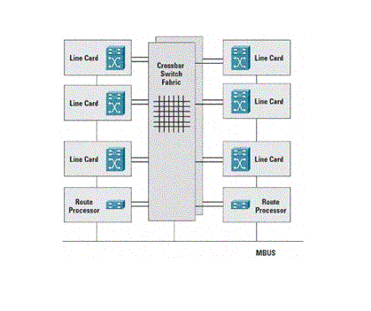 A distributed form of CEF (dCEF) provides the same forwarding capabilities as centralized routers, but on a distributed basis. In this case, each LC has a copy of the CEF Forwarding Information Base (FIB). The FIB is computed by the PRP and pushed to each LC for local use. Thus, packet-forwarding functions are performed autonomously by each LC, and modern LCs (Engine 3-based and later) included ASIC-based hardware-acceleration to forward packets in the fast path.
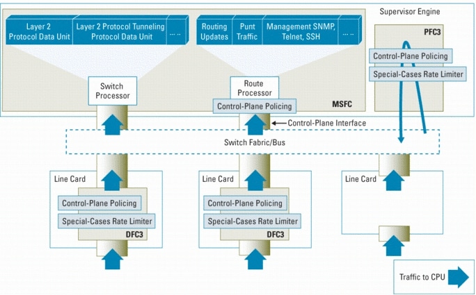 As illustrated in Figure 5, each DFC-based LC and PFC is capable of independently mitigating a line-rate attack in hardware using CoPP and hardware-based special-cases rate-limiters. On the MSFC, CoPP is enforced in software at interrupt level to make sure that only the exact rate configured in the control-plane policy is forwarded to the route processor. Unlike the GSR which can support individual CoPP policies for any LC or the PRP, only a single, global CoPP policy is applied on 6500/7600 platforms. That is, all DFCs and PFCs, as well as the MSFC, are programmed with the same global CoPP policy even though they each police traffic independently.
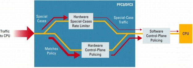 CoPP Deployments