Frame relay – 2-ой уровень модели OSI (Data Link).
- permanent virtual circuits (PVCs)
- switched virtual circuits (SVCs)
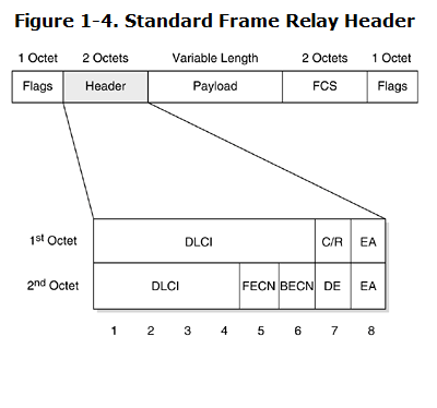 DLCI адрес составляет 10 бит. Возможные значения – от 0 до 1023.
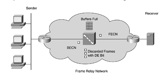
Congestion management
Explicit Congestion Notification Bits:
- Forward explicit congestion notification (FECN)
- Backward explicit congestion notification (BECN)
Discard Eligibility (DE) – если трафик превышает CIR , то устанавливается этот бит.
Использование расширений , таких как Local Management Interface (LMI) позволило использовать следующие возможности:
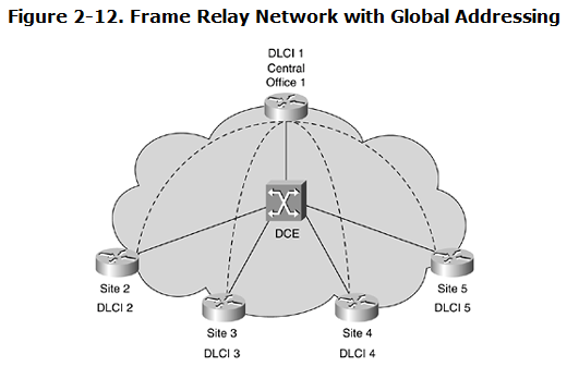
- Global addressing— This gives Frame Relay DLCI global instead of local significance.
- Multicasting— This allows a single frame to be delivered to multiple receivers in the Frame Relay network.
- Virtual Circuit Status Messages— These provide keepalives and status communication mechanisms to allow Frame Relay devices to detect new PVCs or to periodically report the status of its connections.
LMI (Local Management Interface)
The LMI is a standardized suite of protocols that Frame Relay uses to exchange messages and information on the state of a connection. Using the LMI signaling mechanism, both ends of a Frame Relay connection can communicate with each other to determine the status of the PVC, the DLCI value defined for the connection, and whether the interface is active. More recently, functionalities such as congestion management, PVC auto-discovery, multicasting, and address resolution have been added.
LMI exchanges status information on reserved DLCI values 0 and 1023 using special management frames. Three different LMI types are supported on Cisco devices. The Cisco LMI type uses DLCI 1023, whereas both ANSI and ITU LMI types are communicated to DLCI
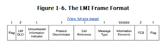
The following listing describes all sections of frame:
- Flags— Delimits the start and end of the LMI frame
- LMI DLCI— Differentiates the frame as an LMI frame instead of a normal Frame Relay frame
- Unnumbered Information Indicator— Sets the poll/final bit to zero
- Protocol Discriminator— Contains a value indicating that this is an LMI frame
- Call Reference— Always contains zero; not used for any purpose
- Message Type— Labels the frame as follows:
- – Status-inquiry message— Allows a user device to inquire about the status of network
- – Status message— Responds to status-inquiry messages; includes keepalives and PVC status messages
- Information Element (IE)— contains a variable number of individual information elements; consist of the following:
- – IE Identifier— Uniquely identifies the IE
- – IE Length— Indicates the length of the IE
- – Data— Consists of one or more bytes containing encapsulated upper-layer data
- Frame Check Sequence (FCS)— Ensures the integrity of the transmitted fram
Common Frame Relay Terminology
| Term | Definition | Description |
|---|---|---|
| CIR | Committed Information Rate | Rate in bps at which the network commits to transfer user data under normal conditions, averaged over a minimum time interval, Tc. |
| EIR | Excess Information Rate | The maximum rate in bps in excess of the insured CIR at which the network attempts to transfer user data under normal conditions, averaged over a minimum time interval, Tc. |
| Bc | Committed Burst | The maximum amount of data in bits that the network commits to transfer, under normal conditions, during a Tc interval. |
| Be | Excess Burst | The maximum amount of data in bits in excess of the Bc that the network attempts to transfer, under normal conditions, during a Tc interval. |
| Tc | Committed Rate Measurement Interval | Tc is computed as Tc = Bc/CIR. |
| DLCI | Data Link Connection Identifier | A unique 10-bit number assigned to a PVC end point in a Frame Relay network to identify a PVC connection. |
| LMI | Local Management Interface | A suite of maintenance protocols for Frame Relay. |
| PVC | Permanent Virtual Circuit | A logical connection that is permanently established. |
| SVC | Switched Virtual Circuit | A logical connection that is established only on demand. |
| VC | Virtual Circuit | A logical connection established between two end points in a network. |
| DCE | Data Circuit-Terminating Equipment | DCE devices provide a clocking signal used to synchronize data transmission between DCE and DTE devices. |
| DTE | Data Terminal Equipment | DTE devices use clocking provided by DCE devices. |
The Cisco IOS supports three different LMI types:
- Cisco
- ANSI Annex D
- Q.933-A Annex A
| Supported LMI Type | DLCI | Developing Organization |
|---|---|---|
| Cisco | 1023 | Gang of Four |
| ANSI Annex D | 0 | ANSI TI.617 |
| Q933A Annex A | 0 | ITU-T (CCITT) |
Global Addressing
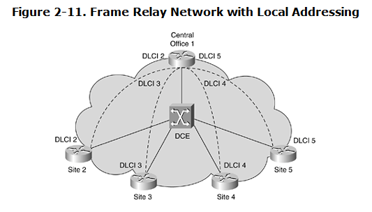
Local Addressing
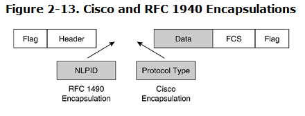
Frame Relay Encapsulation
Frame relay encapsulation :
- Cisco proprietary
- RFC 1490

